I’ve been meaning to try this project out for a while… It’s a basic logic analyser built on the STM32F4DISCOVERY board.
The STM32F4 runs at 168MHz, so we’ve got a fair bit of bandwidth available. Nothing like a real logic analyser, but the project page reports 20MHz. For most of the microcontroller-based work I do, that will be more than sufficient.
The author of LogicDiscovery is Russian, so documentation isn’t easy to find; however Google translate does a good enough job on his descriptive blog that it’s possible to work out how to get started.
While it’s possible to download and compile the source yourself; I didn’t bother. The author has supplied a binary image; so I just downloaded that and flashed it to my discovery board.
$ openocd \
   -f /usr/share/openocd/scripts/board/stm32f4discovery.cfg \
   -c "init" \
   -c "reset halt" \
   -c "sleep 100" \
   -c "wait_halt 2" \
   -c "echo \"--- Writing LogicDiscovery-r12.bin\"" \
   -c "flash write_image erase LogicDiscovery-r12.bin 0x08000000" \
   -c "sleep 100" \
   -c "echo \"--- Verifying\"" \
   -c "verify_image LogicDiscovery-r12.bin 0x08000000" \
   -c "sleep 100" \
   -c "echo \"--- Done\"" \
   -c "resume" \
   -c "shutdown"
Open On-Chip Debugger 0.7.0 (2013-05-15-12:03)
Licensed under GNU GPL v2
For bug reports, read
        http://openocd.sourceforge.net/doc/doxygen/bugs.html
srst_only separate srst_nogate srst_open_drain connect_deassert_srst
Info : This adapter doesn't support configurable speed
Info : STLINK v2 JTAG v14 API v2 SWIM v0 VID 0x0483 PID 0x3748
Info : Target voltage: 2.868772
Info : stm32f4x.cpu: hardware has 6 breakpoints, 4 watchpoints
target state: halted
target halted due to debug-request, current mode: Thread
xPSR: 0x01000000 pc: 0x080038b4 msp: 0x10010000
--- Writing LogicDiscovery-r12.bin
auto erase enabled
Info : device id = 0x10016413
Info : flash size = 1024kbytes
wrote 65536 bytes from file LogicDiscovery-r12.bin in 3.865705s (16.556 KiB/s)
--- Verifying
verified 50196 bytes in 0.579957s (84.523 KiB/s)
--- Done
shutdown command invoked
You can now connect the micro USB cable to your PC and you’ll see a CDC serial port appear.
usb 2-3: USB disconnect, device number 16
usb 2-3: new full-speed USB device number 17 using ohci_hcd
usb 2-3: New USB device found, idVendor=0483, idProduct=5740
usb 2-3: New USB device strings: Mfr=1, Product=2, SerialNumber=3
usb 2-3: Product: STM32 Virtual ComPort in FS Mode
usb 2-3: Manufacturer: STMicroelectronics
usb 2-3: SerialNumber: 00000000050C
cdc_acm 2-3:1.0: This device cannot do calls on its own. It is not a modem.
cdc_acm 2-3:1.0: ttyACM0: USB ACM device
Now we need a way of controlling and reading back the captured data. Fortunately LogicDiscovery implements the standardised SUMP protocol; and even more fortunately there is a nice SUMP client, Open Logic Sniffer (or OLS) that talks that protocol. It’s a Java application, so you’ll need a JDK installed – I had OpenJDK from Debian installed already, and it worked out of the box with the run.sh script that comes with OLS.
You need to be aware of a few limitations that LogicDiscovery imposes, and set up OLS accordingly. In the Begin Capture dialog, do this:
- Port speed, 115200.
- Set Device type to “Open Bench Logic Snifferâ€. You can use “show device metadata†to check LogicDiscovery on the STM32F4 is detected.
- In ‘Acquisition’ sampling rate cannot exceed 20MHz. Setting it higher will sample at 20MHz anyway, but will report all the times wrong.
- Channel Groups, set to “0†for
PD0–PD7; or “0†and “1†forPD0–PD15. - The author says that you can only use 12kB for Recording Size, but it worked okay for me at 24kB. This determines how long your sample buffer is, and OLS tells you the size of the interval in brackets after the selection. This is obviously a function of the buffer size and the sample rate.
- Don’t set any of Test mode, Noise Filter or Run Length Encoding. None of them are (apparently) supported.
- On the “Triggers†tab, you must choose the “SIMPLE†type of trigger, in “Parallel†mode; but other than that you are free to pick anything. The mask field tells the board which pins to detect, and value what edge to match. Only bits 0-15 will be of use because only
PD0–PD15are supported.
As a client, OLS is excellent.
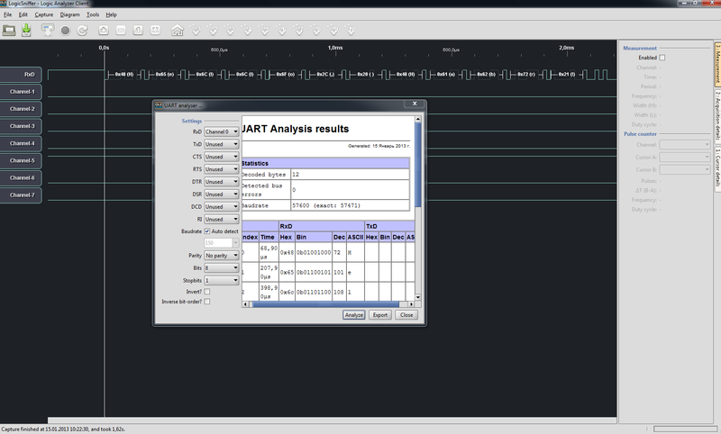
This is it doing a UART decode on a sampled stream. It has analysers for I2C, SPI, JTAG and some others too; but I’ve not got sources of those signals around so I can’t test them. The really high rate implementations of these are out of LogicDiscovery’s league (remember a 20MHz sample rate means 10MHz signals at best); but most microcontrollers won’t use those sorts of rates; and many devices don’t support high rates even if the microcontroller would do it.
One final useful bit of information: the discovery board is not wired for powering from the application USB port that we would use for talking to LogicDiscovery. That means as soon as you unplug the programmer USB port, the board will be powerless. It’s a bit inconvenient to have to plug two USB cables in. You can get around this by looking at the STM32F4DISCOVERY schematic and noting that the VBUS pin from the Micro USB port is connected to PA9. If you connect a jumper wire from PA9 to one of the 5V pins (be careful not to connect to one of the 3V pins), you can power the board from your computer, without needing the programmer USB connected.
In all; I’m delighted. Another tool for the tool box.