|
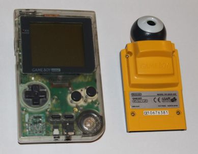
This is the "eye" part of the GameBoy
camera connected to the computer interface. There are 9 wires which have to be disconnected from a small
connector and then joined to a suitable cable such as a ribbon cable.
The signals are +5V, Start, Sin, Load, Reset, CLK, Read, Vout, and
Gnd.
 Initially
I started to make up an interface circuit using only TTL IC’s, this
would be possible but I found that the circuit was becoming large and
untidy. Initially
I started to make up an interface circuit using only TTL IC’s, this
would be possible but I found that the circuit was becoming large and
untidy.
The basic requirements are :
1.
A serial output port to send data to the camera
registers.
2. An output port to send control signals to the
camera.
3. An input port to receive camera signals.
4. An A to D converter to read the analogue
voltage signals from the camera and send as 8-bit data to the
Interak.
As the PIC
16F887 has an A to D converter and
several ports it seemed simpler to use this IC. In addition it meant
that the PIC could control the camera while the Interak was processing
the data into a grayscale image.
A number of
processes have to be carried out to obtain an image from the Image Sensor.
First the
sensor registers have to be set from data held in software to define the image properties.
The computer then sends a Start signal to the PIC (STCAM) this signal is
a very brief pulse from the Interak which was not always picked up by
the PIC. I have added a pulse stretcher (IC3 - 555) to correct this. The
PIC sends Start to the CAM synchronized with the clock and also switches
on the 'Image Sensing' LED - the sensor will
start to scan the view it has at the next rising edge of the Clock.
While image sensing is in progress the Read signal will be set low.
When
sensing is complete READ will be set high. This is the signal to start reading the image data which is produced as
16K analogue voltages. They are sent on the Vout pin in a voltage range
which has been set previously in one of the image sensor registers. (e.g. 0-2V) This is
synchronized with the Clock signal.
Each analogue
voltage (Vout) determines the value of each pixel as a different shade of gray.
These
voltages are converted to digital values before being sent to the
computer.
The
image sensor will continue to acquire images (2nd frame, 3rd frame etc.)
if left, but the current software will capture one frame then reset and
repeat. This keeps the computer in control.
As each converted analogue voltage is sent the PIC will send an
Interrupt signal to the Interak. The computer responds by reading the
data at the input port and storing it. Then an RETI instruction (return
from interrupt) will return the program to a HALT instruction where it
will wait for the next interrupt.
There is no need for an acknowledge signal from the Interak as the PIC
is slow by comparison. I have kept the PIC slow by using an external
4MHz crystal (pins 13 & 14). This gives an internal clock of 1MHz.
The 16F887 also has a programmable internal oscillator which can provide
a range of clock frequencies.
|